


Polarity test for switchgear is essential to ensure that electrical connections within the switchgear operate correctly. This test verifies the alignment of terminals, preventing errors that could lead to system failures. By conducting a polarity test for switchgear, you can maintain proper polarity, reducing risks such as short circuits and equipment damage. Improper connections can result in issues like lack of maintenance, overstressed components, and inadequate fire protection.
Switchgear is a vital component in power distribution, and Zoliov excels in delivering advanced solutions tailored for low and medium voltage applications. With over 20 years of industry expertise, Zoliov provides dependable products such as Ring Main Units and Box Type Substations, ensuring safe and efficient operations.
Key Takeaways
-
Polarity testing is important to keep electrical connections safe and working well.
-
This test stops problems like short circuits and broken equipment by checking terminal alignment.
-
Use tools like a phase tester, multimeter, and polarity tester for accurate results.
-
Always make sure your tools are working correctly before testing.
-
Follow safety rules, like wearing safety gear and turning off power, while testing.
-
Zoliov’s products make testing easier with clear labels and standard compliance.
-
Regular testing makes systems more reliable and helps find problems faster.
-
Test polarity during setup and maintenance to keep systems safe.
What is a Polarity Test for Switchgear?
Definition and Purpose
A polarity test for switchgear ensures that electrical devices connect correctly to the phase conductor. This process prevents hazards like electric shock and equipment malfunction. You can perform this test using two primary methods: visual inspection and continuity testing. Visual inspection involves checking the physical connections, while continuity testing uses instruments to verify the flow of current through the circuit. Both methods confirm that the wiring aligns with the intended design.
Correct polarity is essential for maintaining safety in electrical installations. It reduces risks during maintenance and ensures that the system operates as intended. Without proper polarity, you might encounter issues such as reversed connections, which can lead to dangerous situations or equipment damage.
Key Components of Switchgear Involved in Polarity Testing
Polarity testing involves several critical components within the switchgear. These include:
-
Circuit Breakers: These devices interrupt the flow of electricity during faults. Testing ensures they connect to the correct terminals.
-
Current Transformers (CTs): These measure current levels and protect the system from overloads. Polarity testing verifies their alignment with the circuit.
-
Potential Transformers (PTs): These step down voltage levels for measurement and monitoring. Proper polarity ensures accurate readings.
-
Busbars: These conduct electricity within the switchgear. Testing confirms that connections to the busbars follow the correct sequence.
Each component plays a vital role in the overall functionality of the switchgear. By testing their polarity, you ensure that the system operates safely and efficiently.
How Polarity Testing Ensures Safe Operation
Polarity testing is a cornerstone of electrical safety. It ensures that the current flows in the intended direction, preventing reverse polarity. Reverse polarity can cause severe issues, including short circuits, equipment failure, and even fire hazards.
When you perform a polarity test for switchgear, you verify that all connections align with the design specifications. This step minimizes the risk of accidents during maintenance or operation. For example, if a circuit breaker connects incorrectly, it might fail to trip during a fault, leading to catastrophic damage.
Additionally, polarity testing enhances the reliability of your electrical system. It ensures that protective devices like CTs and PTs function accurately, providing real-time monitoring and fault detection. By conducting this test, you not only safeguard your equipment but also protect personnel working on or near the system.
Tip: Always use the appropriate testing equipment and follow safety guidelines to achieve accurate results during polarity testing.
Equipment Required for Polarity Test
To perform a polarity test for switchgear effectively, you need specific tools. These devices ensure accurate results and help maintain the safety and functionality of your electrical system. Below are the essential pieces of equipment required for this process.
Phase Sequence Tester
A phase sequence tester is crucial for determining the correct phase order in a three-phase system. It ensures that the phases are connected in the proper sequence, which is vital for the safe operation of motors and other equipment. Incorrect phase sequencing can lead to reverse rotation in motors, causing mechanical damage or operational failure.
Modern phase sequence testers are designed for ease of use. They often feature LED indicators or digital displays to show the phase order. Calibration data plays a significant role in the accuracy of these testers. By using auto and cross-correlation coefficients, these devices verify the correct polarity of voltage and current transformers. This ensures that protection relays function properly, reducing the risk of malfunctions.
Tip: Always check the calibration of your phase sequence tester before use to ensure reliable results.
Multimeter
A multimeter is a versatile tool that measures voltage, current, and resistance. It is indispensable for verifying the continuity of electrical connections during a polarity test. You can use it to confirm that the circuit is complete and that there are no breaks or faults in the wiring.
When using a multimeter, ensure it is set to the appropriate measurement mode. For instance, use the voltage mode to check the potential difference between terminals. This step helps you identify any discrepancies in the connections. Additionally, a multimeter can detect reverse polarity, which is critical for preventing equipment damage and ensuring safety.
Note: Always handle the multimeter with care and follow the manufacturer’s instructions to avoid inaccurate readings or equipment damage.
Polarity Tester
A polarity tester is specifically designed to verify the polarity of electrical connections. It checks whether the live, neutral, and ground wires are correctly aligned. This tool is essential for preventing hazards such as electric shock and equipment malfunction.
Polarity testers come in various forms, including plug-in devices and handheld units. They are easy to use and provide quick results. These testers also ensure compliance with electrical codes and standards, which is crucial for maintaining safety in your system. Proper grounding and correct phase and neutral connections minimize the risk of electric shock and protect your equipment from voltage-related damage.
Reminder: Regularly inspect and maintain your polarity tester to ensure it remains in good working condition.
By using these tools, you can perform a polarity test for switchgear with confidence. Each device plays a unique role in verifying the safety and functionality of your electrical system. Always prioritize the use of calibrated and reliable equipment to achieve accurate results.
Step-by-Step Guide to Performing a Polarity Test

Step 1: Phase Sequence Test
The phase sequence test is the first step in verifying the polarity of your switchgear. This test ensures that the three-phase system follows the correct phase order. Incorrect sequencing can cause motors to rotate in the wrong direction, leading to mechanical damage or operational failure.
To perform this test:
-
Connect the phase sequence tester to the terminals of the switchgear.
-
Observe the indicators on the tester. Most devices use LEDs or digital displays to show the phase order.
-
Confirm that the sequence matches the design specifications.
If the sequence is incorrect, adjust the connections to align with the proper order. This step is critical for ensuring the safe and efficient operation of your electrical system.
Tip: Always verify the calibration of your phase sequence tester before starting the test. This ensures accurate results and prevents errors.
Step 2: CT Polarity Test
Current transformers (CTs) play a vital role in electrical systems by linking primary and secondary circuits. Proper CT polarity testing ensures accurate measurements and prevents issues like malfunctioning protection systems.
To conduct a CT polarity test:
-
Identify the primary and secondary terminals of the CT. These are usually marked as P1, P2 (primary), and S1, S2 (secondary).
-
Use a multimeter or a specialized polarity tester to check the alignment of the terminals.
-
Apply a small current to the primary side and observe the output on the secondary side. The direction of the current flow should match the markings on the CT.
Field testing procedures for CT polarity are defined by ANSI/NETA standards and IEEE guidelines. These standards ensure accurate and repeatable measurements, which are crucial for the reliable operation of your system.
-
Why CT Polarity Testing Matters:
-
It prevents measurement errors that could compromise system performance.
-
It ensures that protection systems function correctly during faults.
-
Reminder: Always follow safety protocols when working with CTs. Incorrect handling can lead to inaccurate results or equipment damage.
Step 3: PT Polarity Test
Potential transformers (PTs) reduce high voltage levels to measurable values, making them essential for monitoring and control. A PT polarity test ensures that the voltage connections align correctly, preventing errors in readings.
Here’s how to perform a PT polarity test:
-
Locate the primary and secondary terminals of the PT. These are typically labeled as H1, H2 (primary) and X1, X2 (secondary).
-
Connect a polarity tester or multimeter to the terminals.
-
Apply a low voltage to the primary side and measure the output on the secondary side. The polarity markings should match the voltage flow direction.
Proper PT polarity ensures accurate voltage measurements, which are critical for system monitoring and fault detection. This step also minimizes the risk of equipment malfunction caused by incorrect voltage readings.
Note: Regularly inspect your PTs for wear and tear. Damaged components can affect the accuracy of your polarity test.
By following these steps, you can perform a polarity test for switchgear effectively. Each step ensures that your system operates safely and efficiently, reducing the risk of hazards and equipment failure.
Common Mistakes and Safety Tips for Polarity Testing
Frequent Errors to Avoid
When performing a polarity test for switchgear, certain mistakes can compromise the accuracy of your results or even lead to safety hazards. Avoiding these errors ensures a smooth and reliable testing process:
-
Incorrect Equipment Calibration: Using uncalibrated tools like multimeters or phase sequence testers can produce inaccurate readings. Always verify calibration before starting.
-
Misidentification of Terminals: Confusing primary and secondary terminals on CTs or PTs can lead to incorrect polarity verification. Double-check the labels before connecting.
-
Skipping Visual Inspections: Overlooking physical connections can result in undetected wiring issues. Always inspect connections before testing.
-
Neglecting Safety Protocols: Failing to wear protective gear or ignoring lockout/tagout procedures increases the risk of accidents.
By staying vigilant and addressing these common errors, you can ensure a safer and more effective testing process.
Safety Guidelines for Conducting Tests
Safety should always be your top priority during polarity testing. Follow these guidelines to protect yourself and your equipment:
-
Wear Personal Protective Equipment (PPE): Use insulated gloves, safety goggles, and flame-resistant clothing to minimize risks.
-
De-energize the System: Always disconnect power before connecting or disconnecting testing equipment.
-
Follow Lockout/Tagout Procedures: Secure the system to prevent accidental re-energization during testing.
-
Use Proper Tools: Ensure all testing devices are rated for the voltage and current levels of your system.
-
Maintain a Safe Distance: Keep a safe distance from live components to avoid electric shock.
Adhering to these safety measures not only protects you but also ensures the integrity of your electrical system.
Best Practices for Accurate and Reliable Results
To achieve precise and dependable results, follow these best practices during polarity testing:
-
Verify Manufacturer Specifications: Check individual modules against the manufacturer’s guidelines to identify any discrepancies.
-
Ensure Correct Series Connections: Confirm that modules in a string are connected with the correct polarity.
-
Inspect Combiner Box Inputs and Outputs: Verify the polarity and voltage levels of each string before combining them.
-
Check Load-Break Disconnect Terminals: Confirm the expected voltage from the combiner box.
-
Test Inverter DC Inputs: Ensure the voltage from the load-break disconnect matches expectations.
The table below highlights industry standards that define best practices for polarity testing:
|
Standard |
Description |
|---|---|
|
IEC 62446 |
Minimum requirements for system documentation, commissioning tests, and inspection of grid-connected photovoltaic systems. |
|
IEC 61215 |
Design qualification and type approval for terrestrial photovoltaic (PV) modules. |
|
Local electrical codes |
Compliance with local regulations and utility requirements to ensure safety and reliability. |
By following these practices and adhering to industry standards, you can enhance the accuracy and reliability of your polarity test for switchgear.
Pro Tip: Regularly maintain and calibrate your testing equipment to ensure consistent performance.
Zoliov’s Role in Ensuring Safe and Efficient Switchgear
Overview of Zoliov’s Power Distribution Equipment
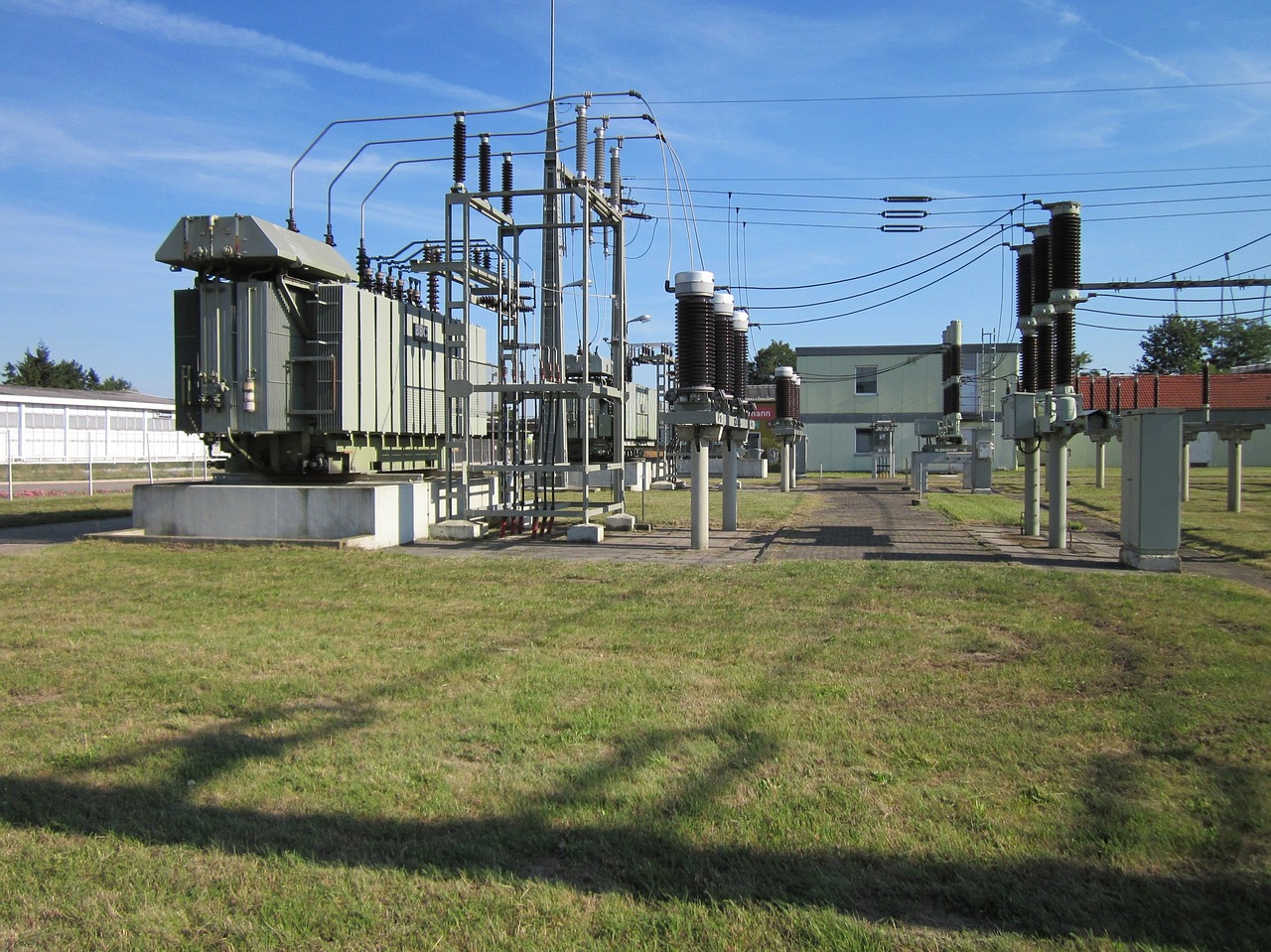
Zoliov has established itself as a trusted name in the power distribution industry, offering a wide range of products designed for both low and medium voltage applications. With over two decades of experience, Zoliov provides solutions that prioritize safety, efficiency, and durability. Their product lineup includes advanced switchgear, Ring Main Units (RMUs), Box Type Substations, and Power Transformers. Each product is engineered to meet the demands of modern electrical systems while ensuring minimal maintenance requirements.
Zoliov’s equipment stands out for its adaptability. Whether you need a compact solution like the Box Type Substation or robust RMUs for outdoor use, Zoliov delivers products tailored to your specific needs. Their commitment to innovation ensures that every product integrates seamlessly into your power network, enhancing overall system performance.
Polarity testing is essential for maintaining the safety and efficiency of switchgear systems. It ensures proper electrical connections, preventing hazards like equipment failure and short circuits. By following the outlined procedure, you can verify the alignment of terminals and enhance system reliability. Polarity testing also supports accurate monitoring and fault detection, safeguarding both equipment and personnel. Zoliov’s advanced power distribution equipment simplifies this process with clear terminal labeling and compliance with industry standards. Choosing Zoliov ensures you receive reliable products tailored to your needs, backed by exceptional customer support.
Contact Zoliov
Find more details about Power Distribution Solution
FAQ
What is the purpose of a polarity test for switchgear?
A polarity test ensures that electrical connections in switchgear align correctly. This prevents hazards like short circuits, equipment failure, and electric shock. It also verifies that the system operates safely and efficiently.
Can I perform a polarity test without professional help?
You can perform basic polarity tests if you have the right tools and knowledge. However, for complex systems, hiring a certified technician ensures accuracy and safety.
What happens if polarity is incorrect in switchgear?
Incorrect polarity can cause reverse current flow, leading to equipment damage, inaccurate readings, or even fire hazards. It compromises the safety and functionality of the electrical system.
How often should polarity tests be conducted?
Perform polarity tests during installation, maintenance, or system upgrades. Regular testing ensures the system remains safe and operates as intended.
What tools are essential for polarity testing?
You need a phase sequence tester, multimeter, and polarity tester. These tools help verify connections, measure voltage, and ensure proper alignment of terminals.
Are Zoliov products compatible with polarity testing?
Yes, Zoliov products are designed for easy polarity testing. Clear terminal labeling and compliance with industry standards simplify the process and ensure accurate results.
Why is safety gear important during polarity testing?
Safety gear like insulated gloves and goggles protects you from electric shock and other hazards. It ensures a safe testing environment, especially when working with live systems.
How does polarity testing improve system reliability?
Polarity testing ensures correct connections, which enhances the accuracy of monitoring devices like CTs and PTs. This improves fault detection and reduces the risk of system failures.
Tip: Always follow safety protocols and use calibrated tools for reliable polarity testing results.